Introduction
Film photography is expensive. It doesn't get any cheaper as your negative size increases. This is especially true when you want to do more than scan photos for the web. Printing is expensive. I started out with an enlarger to handle 6x6cm negatives that I bought for £15. This has served me well. print as large as 16x20 regularly but new paper (B and W) is about £4.00 a sheet, and I can use 10-15 sheets getting to a print I like.
When I got a 4x5 large format camera and I had to be satisfied with scanning and contact printing. And despite claims that contacts prints in the 4x5 inch size can be 'jewels' it is not as satisfying as larger prints. Then I was given an
old 4x5 enlarger for free. (Yes I know this doesn't sound too expensive. But I now have 2 dark rooms and I consume a lot of space!)
Next I get two new cameras both Fuji's, one is 6x9cm image the other is 6x17cm. Now 6x9 fits my 4x5 (10x12cm) enlarger but the 6x17cm negatives demands a 5x7 (12x18cm) enlarger. I can print up to 6x12cm crops of the negative on the 4x5 enlarger which is probably not too bad but I lose almost a whole medium format frame of the subject. How to display or present these photos?
Color prints I have to scan and get printed. This is all costly as illustrated below.
Process 6x9cm 6x17cm 10x12 (4x5")
Film (Velvia 100). £0.75 £1.50 £4.50
Dev. £0.60 £1.20 £3.20
Scan £19.00 £29.0 £29.00
Print (16x20") £10.38 £10.38 £10.38
Total £30.73 £42.08 £47.08
When researching the Fuji G617 there were a number of comments about what little gems the color transparencies were especially in Velvia. This lead me to think that one could display transparencies mounted in a frame. (It remains to be seen if this is cheaper than a framed print.) With only a bright white card behind the transparency the image is visible under good ambient light.
Back-lighting Transparencies
I wanted to go further however and try back-lighting the transparency. The trouble with this is providing the power. I decided to experiment with a solar powered light using dismantled garden lights. These are available for less than a £1. They have a small battery solar cell and an LED. A single LED is just about bright enough. Alas further research indicated that while they charge sufficiently outdoors the energy from the sun has thousands of times more energy and that indoors it might take a panel the size of a coffee table to reliably light a transparency.
My next step is to use a rechargeable battery. If I could get say a week's life out of one I could think of recharging as winding a clock. It would still allow wall mounting when not charging. I also decided to also try a USB power connector so it could be mains or battery powered.
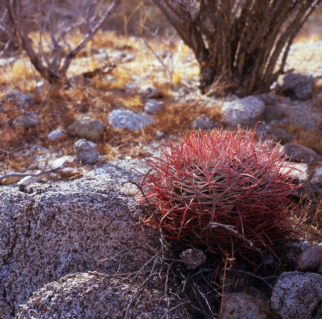
I decided to prototype this with a 6x6cm Velvia transparency.
 |
| Test transparency |
I bought a small box frame from Hobbycraft here in the UK for a 7.5x7.5cm picture. I cut a matte frame to fit the transparency and taped the transparency to it. This I put behind the glass and put a cut piece of tracing paper behind that to provide some difusion of the LED light.
The box frame I bought is only 1.5 cm deep and so struggles to hold the battery and keep the LED a good distance from the diffuser. The LED has a cone of light and works best well behind the diffusion and transparency. To help with the light diffusion problem I have bought some backlight diffusers used on small LCD displays. They provide a rectangle of uniform backlight from a single LED. They are also considerably brighter than the garden light.
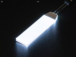 |
| Backlight (12x48mm) |
I rescued an old Lithium Polymer (LiPo) battery from an old phone. The backlights are rated at 3.2v at about 15mA. A LiPo battery is about 3.7v so Ohm's law says one needs a resistor of (3.7v-3.2v)/.015A= 33 Ohms.
Testing the Idea
I placed this between my transparency diffuser sandwich and the back of the frame. Normally this is a piece of MDF but I placed bright white card over this to give more reflection. The result looks great.
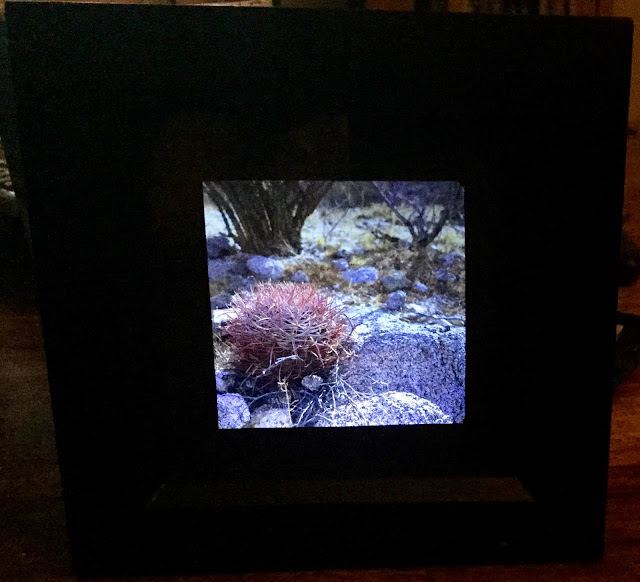 |
| Illuminated transparency (6x6cm) in frame (black) |
Color Temperature
The image is very bright. The back-light rests on the bottom of the frame pointing up in the photo shown. I found it gives more uniform illumination if directed to the white backing card at the back of the frame. The backing card has another advantage in that the color temperature can be changed. The photo above exhibits well my impression that the color temperature of the back-light is too high (blue). The back-light datasheet give CIE chromaticity coordinates of x=.27 y=.28. Below is the CIE plot and I have superimposed the datasheet coordinates in red over this.
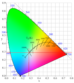 |
| CIE plot with backlight color temperature overlaid in red lines |
The curved black line on a CIE plot is the color temperature with the intersecting lines give the color temperature running from blue on the left (higher color temperature) to red (lower color temperature) on the right. My plot puts the color temp at 10,000K very blue! Daylight is thought of as being 6500K though photographic (daylight) film is balanced for 5500K.
Another way to see this is to look at the spectral response from the back-light datasheet. I copied this chart and overlaid it with the colors that the wavelengths correspond to. This makes it easier to visualize. Most 'white' LEDs are not like incandescent bulbs in that they typically construct light using 2 or more color phosphors. (Incandescent light is more continuous becoming bluer at higher temperatures.)
In the chart below the strongest peak is around 450 nm which accounts for the blue or high color temperature. There is a second smaller peak in the green through orange region which his why it does not appear completely blue.
This means a significant shift to warmer color temperature is required. The original plan was to print colored backing cards to achieve the right shift. This looks to be most likely orange as quite a shift is required. An alternative is to place a piece of orange gel across the back-light itself. I like the idea of using an inkjet printer backing paper as I can manipulate the color.
 |
| Warming gradient |
It also gives the chance to print a gradient from the bottom of the card upward dark to light to equalize the lighting across the transparency with the light source located in the bottom. The issue I anticipate is I am getting cooler as it moves to the top. It might be better to overlay a neutral density gradient on a constant warming color. It might look like this...
 |
| Color temperature neutral warming gradient |
These I have generated in Word using the gradient and transparency function in the drawing menu.
Updated Color Temperature Correction
I finally settled on what is called CTO film (Color Temperature Orange) which is used in filming to adjust light from daylight to tungsten. It comes in 3 grades 1/4, 1/2, and Full. I found full sheets of the transparent material on ebay. Since this film is orange then it cuts the amount of blue light from the back-light. How much is determined by the strength of 1/4 to full. I experimented and found the 1/4 strength to be sufficient for the 6x17 image below. I merely put the film against the diffuser plastic as part of the image sandwich.
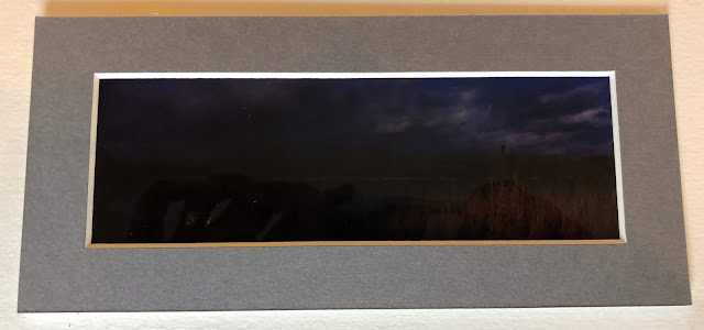
Here are the before and after images. Both images look OK however the second has purer whites and the grays are more accurate. I also find the reeds have a more realistic warmth to them.
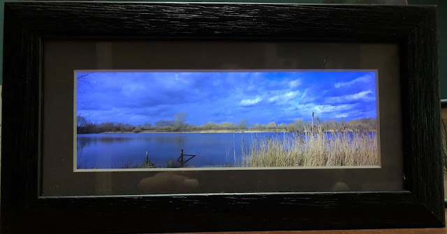 |
| Before Color Correction |
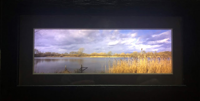 |
| After Color Correction |
Frames
Researching how to put this into broader use I have researched online framing companies. There are some specific constraints they have on small sizes of frames and mounts. Box frames are what I am looking for as they have the depth to accommodate the gubbins for the backlight. I am shooting for the smallest frame I can fit this in. I anticipate however that multiple images could be displayed in a larger multiple aperture frame.
Frames seem to have minimum width/heights of 80mm and mattes need at least 20mm of width. The frame itself can be as small as 20mm width. The depth is in the range of 37-50mm. So for a 60mm negative this gives a mount card minimum of 20mm on each side. For an example of a Fuji G617 transparency (60mmx170mm) this gives a mount of 100mm high and 210mm wide. The frame is a 132mm high and 157.
Let’s Make One!
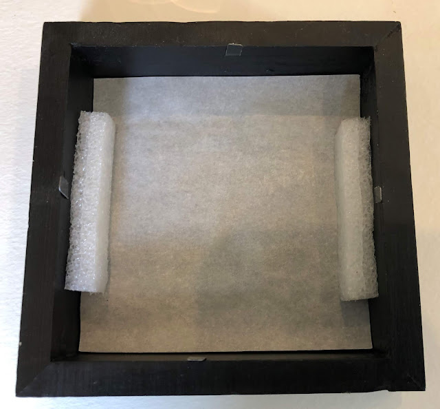
This was the next thing to tackle using what I had learned so far. I started out using 2 diffused light sources this time due to the longer image. I bought the box frame in the dimensions above with the 6x17 matte board.
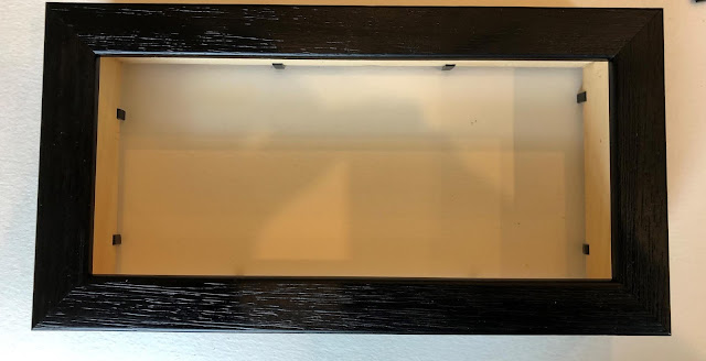 |
| Front of purchased box frame |
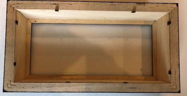 |
| Back of purchased box frame |
I also selected my transparency, again a Velvia 100 image. This I taped to the back of the matte board.
 |
| Matte board with transparency taped to back |
The perspex glazing is part of the image sandwich for the front. Next I cut from some translucent acrylic sheeting a diffuser. This is the back of the image sandwich. I experimented with keeping this about 8mm from the image at first but found it works best right against the transparency as the back-lights only then creates even illumination.
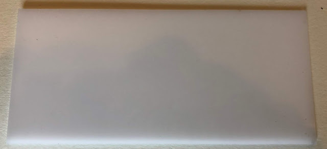 |
| Acrylic diffuser |
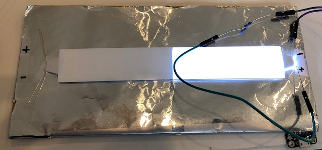
My next step was to mount the back-lights. These I adhered to the MDF backing board that came with the frame that first I coated in foil to improve the brightness. They are not as wide or long as the image so the diffuser I show above is vital even though they have their diffuser over the top. (It might be tempting to remove the back-light diffuser film to improve the brightness even more. It should work but I did not try it. Each diffuser loses about 20% of the light.)
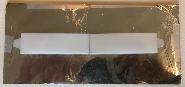 |
| Mounted back-lights and foil on MDF panel |
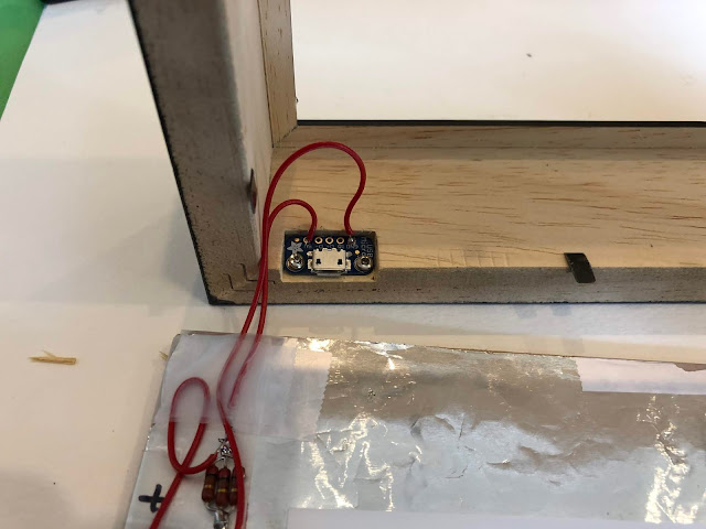
I planned to power this from a normal Micro USB connector so I could use a power bank or a phone charger to run it. I used a little breakout board from
Adafruit. It looks like this.
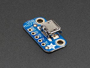 |
| Micro USB breakout board. |
It has easy to solder holes and a couple of screw mounting holes. (You only need to use the GND and +5V pads.) Next I chiseled out a little nest for the board in the bottom of the frame so the connector is exposed.
 |
| Chiseled slot for USB breakout board |
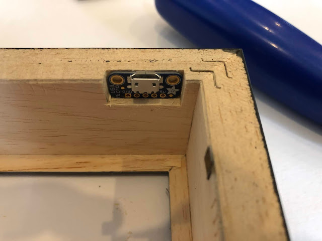 |
| A satisfying fit... |
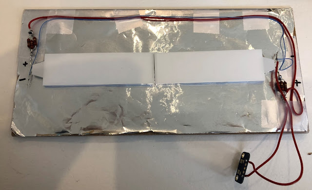
Next it is time to wire the whole thing up. Looking again at the datasheet for the back-light the specs to drive the back-light safely are 3.2 v at about 20-25 mA for full brightness and long life. This means I need to put a resistor in series for each LED to limit the current. The calculations are from Ohm's law as follows. USB gives about 5 volts. The voltage drop needed is 5-3.2=1.8 v. V=I x R where V=1.8 v and I =.025 Amp (25 mA) and R is the resistor we need. So R=V/I R= 1.8/.025 = 72 ohms. I do not have a very good selection of resistors at home so the best I could find was 200 ohm resistors. By soldering 3 in parallel I get 200/3 = 67 ohms which gives a little too high current at 27 mA but less than the max spec of 30 mA so I think I am OK.
First I confirm the polarity of the LEDs in the back-lights and mark the wires accordingly. I just rigged up a battery to make sure I got this right. LEDs unlike incandescent light bulbs have a polarity. They only work when wired the right way around.
 |
| Marking polarity of back-lights |
Next time to warm up the soldering iron and wire it up.
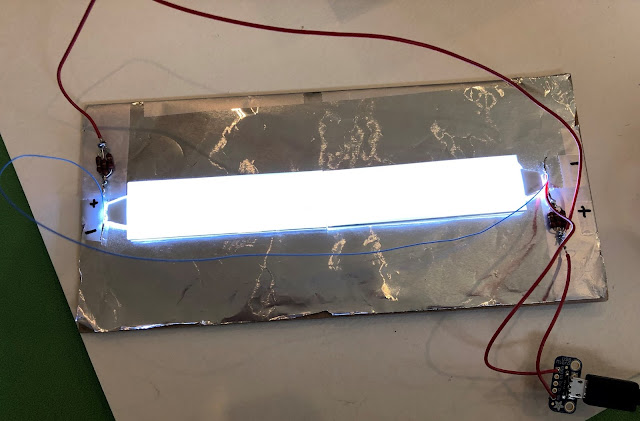 |
| Wired up and tested. |
In the photo the wiring is apparent. Note the bundle of 200 ohm resistors on the + terminals. Now time to put it all together.
 |
| Tidy-up the wires |
 |
| Screw the USB connector to the frame |
I next needed to cut the standoffs that keeps the backboard and back-lights separated from the image sandwich. This I cut from white foam-core board. White again to maximize brightness. (I did not try and warm the color temperature on this one as the scene is fairly blue and so it didn't seem necessary.
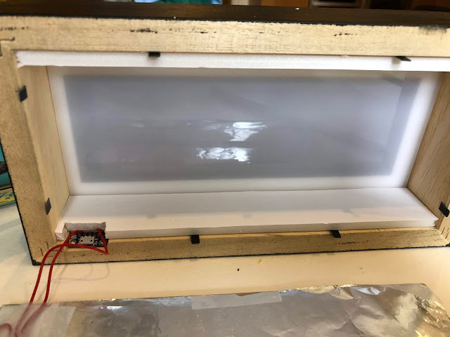 |
| White foam board spacers in place |
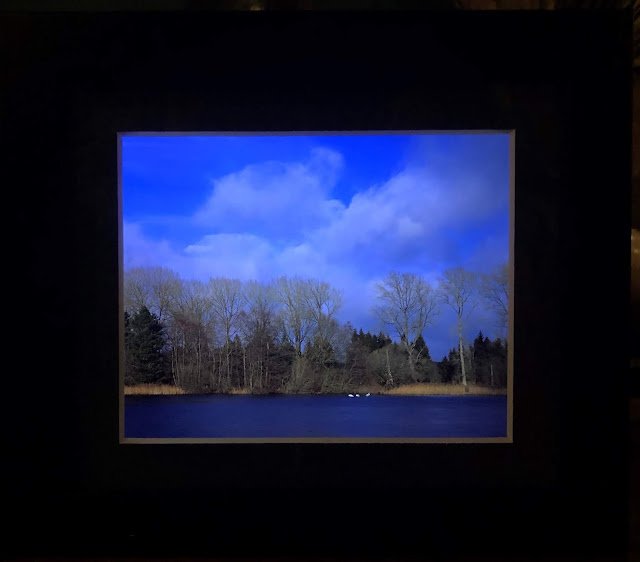
I then installed the backing board and bent over the metal tabs. Plugged it in and put it on display.
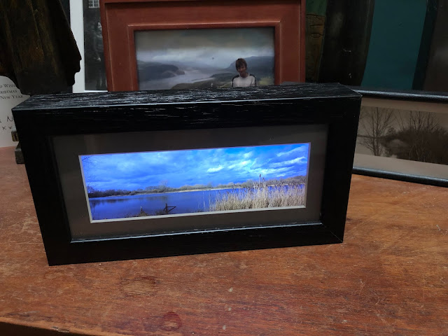 |
| Final result |
It looks great!
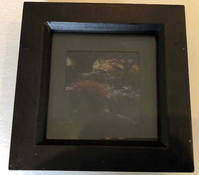
The Original Barrel Cactus Transparency Frame: Completed
I finally finished this one even though I started the article with it. It allowed me to try out ideas, though I did not put all of the principles into practice. As I said I mounted the image on a mask using tape then placed the tracing paper behind this to act as a diffuser.
 |
| Back View: Tracing paper diffuser sandwiched over film, mask, perspex window |
 |
| Front View |
Next I chiseled out a slot for the USB connector into the frame. I also wired up and tested the circuit. This was the same as above including the same 3x 200 ohm resistor setup.
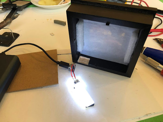 |
| Notch for USB connector and testing the electronics |
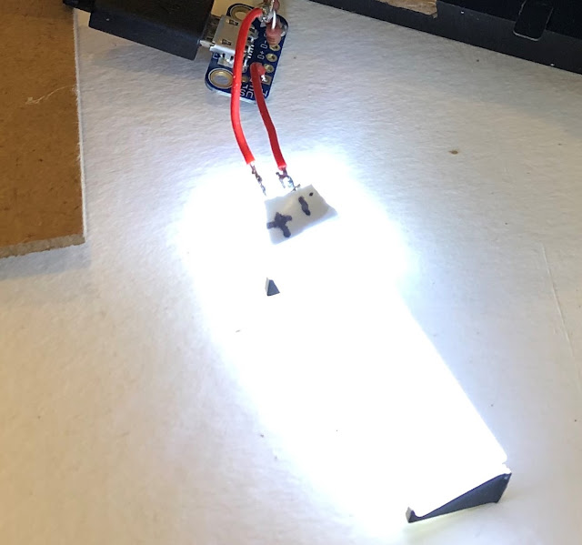 |
| Back-light detail with angle mount on end |
Shown in the above photo is the black angle that is one each end of the back-light. This shines the light up and towards the backing board which has white card taped to it to achieve a more even illumination. Also note I cut away the diffuser attached to the top of the back-light reasoning it was reducing the light output and was needed as the light is all indirect. I did leave the section that is foil backed (I wrote + and - on it) that sits over the LED as this is intensely bright.
Next it was time to test it. The color temperature as discussed above was very high (blue) again with just the white card. I decided to try a simpler trick and used an orange colored pencil to color the area where the light shines the brightest. It does tone down the blueness.
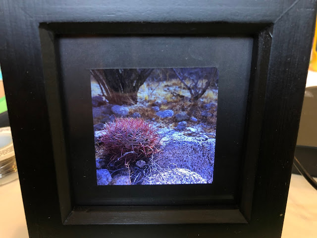 |
| High (blue) color temperature |
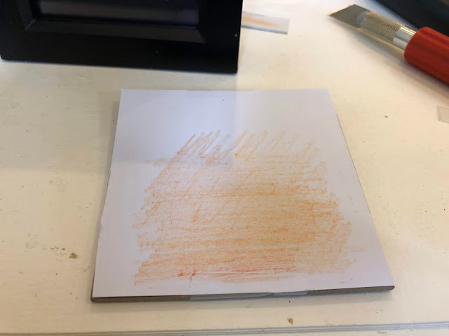 |
| Orange pencil markings to lower color temperature |
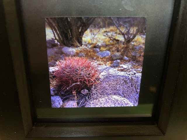 |
| A warmer color temperature result |
The result is great. Here it is in our kitchen.
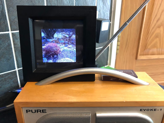 |
| Finished result |
A 4x5 Version
Finally I made a 4x5 version. (Velvia 100 one stop underexposed)
 |
| 4x5 Transparency Presentation Frame |
For comparison here it is beside the 6x17 version.
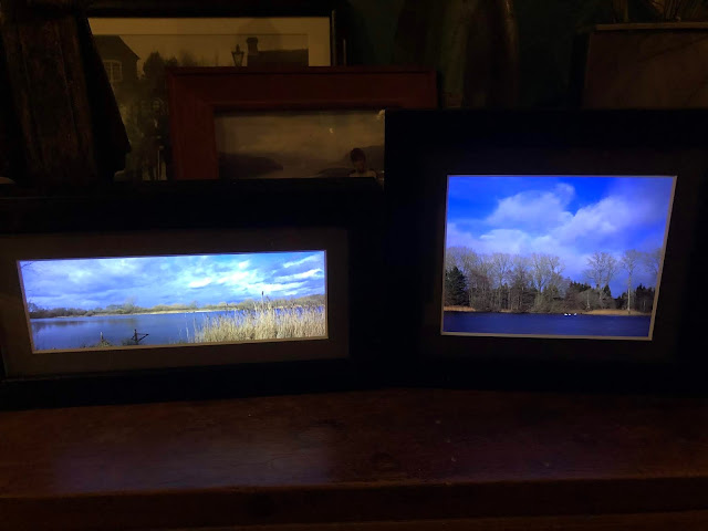 |
| Side-by-side comparison |


Comments